|
Размер: 13170
Комментарий:
|
← Версия 9 от 2019-12-13 19:00:47 ⇥
Размер: 13190
Комментарий:
|
| Удаления помечены так. | Добавления помечены так. |
| Строка 86: | Строка 86: |
| Produce this ☺ : | Produces this ☺ : |
| Строка 90: | Строка 90: |
| Input is more «realistic»: there's no way just to press a button and get __a nember__: we need DEMUX. We can get only bit scale resembles an ''one row'' of buttons (1 is on). So: | Input is more «realistic»: there's no way just to press a button and get ''a number'': we need DEMUX. We can get only bit scale resembles an ''one row'' of buttons (1 is on). So: |
| Строка 105: | Строка 105: |
| <<Anchor(BUG)>> '''WARNING''': thiere is a bug in Mars/Digital lab, that cause total hang when polling permanently. To prevent this, run Mars in «30 intructions per second» mode (upper right slider): {{attachment:RunSpeed.png}} |
|
| Строка 106: | Строка 111: |
'''WARNING''': thiere is a bug in Mars/Digital lab, that cause total hang when polling permanently. To prevent this, run Mars in «30 intructions per second» mode (upper right slider): {{attachment:RunSpeed.png}} |
08. Polling and MMIO
Input/output — data flow in and out the whole system.
Performed by external devices
Such a device is to be controlled
- Variants: storage device (exact IO), transmission device (network, sync etc.)
- Examples:
- I: mouse, keyboard, mic
- O: Graphics, phones
- IO: console, storage, NIC, ...
⇒ External devices is heavily varied by complexity
Methods of device control
How to control:
- Unified with CPU (programming directly from RAM by special instructions)
- Too complex / too different
- Unified control, but arbitrary semantics
E. g. any control channel (think of wire set) is numbered. A number is called port.
There's two instructions only: in from_port, dst_byte and out to_port, src_byte
- Single control action is actually a series:
out data_port command — «next out is specific data»
out data_port data — «that's you specific data»
- and more complex (sync, multibyte etc.)
- Data interpretation depends on device type completely
- MMIO: all/part of device memory is mapped to the specific region of address space
- There is no special instructions to access/control devices
- There is no «joint» memory: operations on MMIO addresses is performed by different hardware, they can be slower, asynchronous etc.
- Also can be used as «device registers», like ports
- Control registers — write commands
- Data registers — read/write data
- Status registers — check if device is in appropriate state (e. g. have new data, done with previous I/O, ready to operate etc.)
MMIO and DMA
What's new on CPU:
Arbitrage: if many device want to update memory, which goes first
- Map device to memory region
MIPS: MMIO starts from 0xffff0000
- Turn memory operation into certain hardware command
- Capture device state and render it at memory
- Data transfer
It's not good to force CPU make all the data transfer. We may provide more complex device, that can do direct memory access (DMA) by itself.
DMA problems:
- Complex arbitrage
- Operation done/error/etc. signalling
We need to separate device/memory access unit (so called bus)
Polling
Polling is technique of data transfer based on periodical checking if the device is ready to accept data (write polling), or having data to be extracted (read polling) before performing IO operation.
- Set up the device
- While device is not ready:
- do something irrelevant
- go to (2)
- If it's ready:
- Perform an IO
- Reset device if needed
Note restrictions on «do something irrelevant»:
- As all this is for IO, we can hardly imagine, what is relevant, what is not
- We need to cut «irrelevant actions» down to fixed period between checks
Example: Mars Digital Lab Sim
«Digital Lab Sim» is virtual emulated device. If consists of keypad and light segments. Any queer designs of this device only slightly resembles real life twisted ones.

0xFFFF0010 |
W |
command right seven segment display (each bit corresponds a segment) |
0xFFFF0011 |
W |
command left seven segment display (same) |
0xFFFF0012 |
W |
command row number (bits 0-3) / enable keyboard interrupt (bit 7) |
0xFFFF0013 |
W |
counter interruption enable |
0xFFFF0014 |
R |
receive row (bits 0-3) and column (4-7) of the key pressed |
- Device is activated in the emulator after «Connect» button pressed.
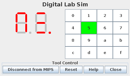
There's no way to read from LED
Writing a byte to 0xFFFF0010 turns segment on if corresponded bit is !, of otherwise
Example:
Produces this ☺ :

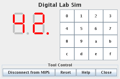
Input is more «realistic»: there's no way just to press a button and get a number: we need DEMUX. We can get only bit scale resembles an one row of buttons (1 is on). So:
Write an only bit corresponded to raw (bits are 1— "0-1-2-3", 2—"4-5-6-7", 4—"8-9-a-b" and 8—"c-d-e-f") to 0xffff0012
Read bitscale from 0xffff0014.
- if no pressed buttons in this raw, returns 0
- if there was pressed button in this raw, returns bitscale with
- bits 0-3 correspond to raw
- bits 4-7 corresponded to column (0x10,0x20,0x40 и 0x80 for «0», «1», «2» and «3», for example)
- Code looks like this:
- There are no errors if any number except for 1,2,4 or 8 is written to xffff0012, but, for being extremely dumb, it always returns 0.
WARNING: thiere is a bug in Mars/Digital lab, that cause total hang when polling permanently. To prevent this, run Mars in «30 intructions per second» mode (upper right slider):

Example: write scanned value directly from keyboard to right LED (makes almost no sense, though). Left LED is set to numbers of clicks.
   1         lui     $t8 0xffff              # MMIO base
   2         move    $t7 $zero               # counter
   3         move    $t6 $zero               # previous value
   4 loop:
   5         move    $t1 $zero               # scans accumulator
   6         li      $t0 1                   # 1st row
   7         sb      $t0 0x12($t8)           # scan
   8         lb      $t0 0x14($t8)           # get result
   9         or      $t1 $t1 $t0             # apply it to accumulator
  10         li      $t0 2                   # 1nd row
  11         sb      $t0 0x12($t8)
  12         lb      $t0 0x14($t8)
  13         or      $t1 $t1 $t0
  14         li      $t0 4                   # third row
  15         sb      $t0 0x12($t8)
  16         lb      $t0 0x14($t8)
  17         or      $t1 $t1 $t0
  18         li      $t0 8                   # fourth row
  19         sb      $t0 0x12($t8)
  20         lb      $t0 0x14($t8)
  21         or      $t1 $t1 $t0
  22         beq     $t1 $t6 same
  23         sb      $t1 0x10($t8)           # write accumulator to LED
  24         move    $a0 $t1                 # print binary
  25         li      $v0 35
  26         syscall
  27         li      $a0 10
  28         li      $v0 11
  29         syscall
  30         addi    $t7 $t7 1               # counter increment
  31         sb      $t7 0x11($t8)           # write counter to another LED
  32         move    $t6 $t1
  33 same:   ble     $t7 20 loop
  34
  35         li      $v0 10
  36         syscall
- There's no «do smth irrelevant» part in this program
- ⇒ the program eats 100% CPU while in active wait
you may use sleep() syscall (32, wait) to redirect execution flow back to kernel until timeout is expired
Bitmap Display
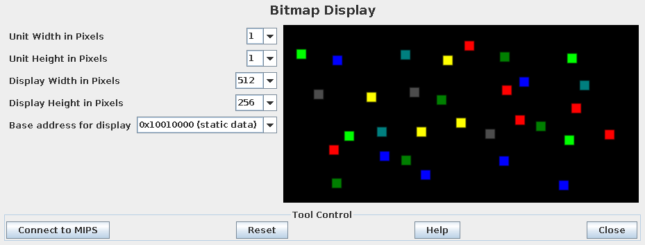
Bitmap Display is graphical device, which videomemory is mapped to certain address space region. Mars default is out of MMIO region (actuallym standard .data, 0x10010000), but it's configurable.

Every word is pixel in 0x00RRGGBB format (more on RGB)
- First pixel is upper left, then all the pixels are mapped continuously from left to right, then down the next raw leftmost dot, etc.)
- Screen is resizable, and pixel size is resizable, do not be confused
Memory usage: ALL = !DisplayWidth * !DisplayHeight * 4 / (!UnitWidth * !UnitHeight)
- the X:Y dot:
X = (Offset / 4) % (DisplayWidth / UnitWidth)
Y = (Offset / 4) / (DisplayWidth / UnitWidth)
Offset of X:Y dot: Offset = Y*!DisplayWidth*4/UnitWidth+X*4
Example: color stars
   1 .eqv    ALLSIZE 0x20000                 # videomemory size (in words)
   2 .eqv    BASE    0x10010000              # MMIO base
   3 .text
   4 again:  move    $a0 $zero
   5         li      $a1 ALLSIZE             # Max 512*Y+X + 1
   6         li      $v0 42
   7         syscall                         # random 512*Y+X
   8         sll     $t2 $a0 2               # make an address by multiplying to 4
   9         move    $a0 $zero
  10         li      $a1 0x1000000           # MAX RGB value + 1
  11         li      $v0 42
  12         syscall                         # random color
  13         sw      $a0 BASE($t2)
  14         j       again
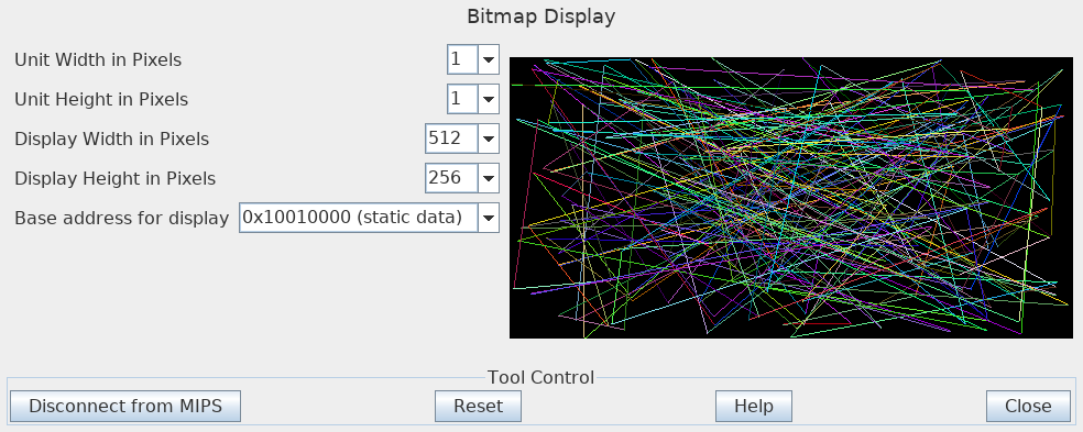
Example: color lines
Set up constants:
We chose 0x10010000 as MMIO base, so we need to select another address for .data section. Let it be global data section (it is unused until we want run more than one task in one memory).
Subroutine that colors a dot with a predefined color, and keeps coordinates taken:
Some macros: push/pop; conventional prologue — subroutine, conventional epilogue — return, and hrandom — make a random value within range given
   1 .macro  push    %r
   2         addi    $sp $sp -4
   3         sw      %r ($sp)
   4 .end_macro
   5
   6 .macro  pop     %r
   7         lw      %r ($sp)
   8         addi    $sp $sp 4
   9 .end_macro
  10
  11 .macro  subroutine
  12         push    $ra
  13         push    $s0
  14         push    $s1
  15         push    $s2
  16         push    $s3
  17         push    $s4
  18         push    $s5
  19         push    $s6
  20         push    $s7
  21         push    $fp
  22         move    $fp $sp
  23 .end_macro
  24
  25 .macro  return
  26         move    $sp $fp
  27         pop     $fp
  28         pop     $s7
  29         pop     $s6
  30         pop     $s5
  31         pop     $s4
  32         pop     $s3
  33         pop     $s2
  34         pop     $s1
  35         pop     $s0
  36         pop     $ra
  37         jr      $ra
  38 .end_macro
  39
  40 .macro  hrandom %range %var
  41         li      $a0 0
  42         li      $a1 %range
  43         li      $v0 42
  44         syscall
  45         sh      $a0 %var
  46 .end_macro
Subroutine that draws a line (from stored coordinates to new given ones):
   1         # draw a line from current x,y to x1,y1 given
   2         # $a0=x1 $a1=y1
   3 lineto: subroutine
   4         lh      $s0 X           # X0
   5         lh      $s1 Y           # Y0
   6         move    $s2 $a0         # X1
   7         move    $s3 $a1         # Y1
   8         sub     $s4 $s2 $s0     # W
   9         abs     $t0 $s4
  10         sub     $s5 $s3 $s1     # H
  11         abs     $t1 $s5
  12         move    $s6 $t0         # horizontal size
  13         bge     $t0 $t1 xmax
  14         move    $s6 $t1         # vertical size is greater
  15 xmax:   move    $s7 $zero       # step i
  16 loop:   bgt     $s7 $s6 done    # X1:Y1 is reached?
  17         # X=X0+W*i/N
  18         mul     $t0 $s4 $s7
  19         div     $t0 $s6
  20         mflo    $t0
  21         add     $a0 $t0 $s0     # new X
  22         # Y=Y0+H*i/N
  23         mul     $t2 $s5 $s7
  24         div     $t2 $s6
  25         mflo    $t2
  26         add     $a1 $t2 $s1     # new Y
  27         jal     dot             # draw a dot
  28         addi    $s7 $s7 1
  29         j       loop
  30 done:
  31         sh      $s2 X
  32         sh      $s3 Y
  33         return
The subroutine stores new X1,Y1 as current ones. This works like a kind of dummy «turtle graphics».
An finally, the program itself:
   1         # Make a bright enough random color
   2 randomcolor:
   3         li      $t0 0
   4 rcnext: li      $a0 0           # B, G, R
   5         li      $a1 0x10        # random 0…16
   6         li      $v0 42
   7         syscall
   8         sll     $a0 $a0 4       # =0…256 step 16, more bright
   9         sb      $a0 Color($t0)
  10         addi    $t0 $t0 1
  11         blt     $t0 3 rcnext
  12         jr      $ra
  13 .data
  14 nx:     .half   0
  15 ny:     .half   0
  16
  17 .text
  18 .globl  main
  19 main:
  20         hrandom WIDTH X
  21         hrandom HEIGHT Y
  22
  23 forever:
  24         jal     randomcolor
  25
  26         hrandom WIDTH nx
  27         hrandom HEIGHT ny
  28
  29         move    $a1 $a0
  30         lh      $a0 nx
  31         jal     lineto
  32         j       forever
Note:
This construction commands Mars to start from man label instead of first instruction in .text section
.globl  main
main:
- You also need to turn «Initialize Program Counter to global 'main' if defined» Mars setting on

GPU
CPU is slow to perform specific multimedia operations ⇒ GPU
H/W
- Make «Color lines» example run on your computer. Checkpoints:
Do not forget to turn «Initialize Program Counter to global 'main' if defined» Mars setting on
What .data 0x10008000 directive does?
What does 0x00RRGGBB mean?
How randomcolor subroutine works?
How many iterations is needed to draw a line? Why we choose X1-X0 or Y1-Y0?
EJudge: EightSectors 'Eight sectors'
Input:Write a progam that inputs 8 integers and colours Bitmap Display with size 128×128 dots based on 0x10010000 like this:

Numbers here indicate color number, you do not need to draw them!
Please note the corners:
 ,
,  ,
,  ,
,  and the center:
  . To see this better you can scale Bitmap Display «size in pixels» by 4 (this do not affects program).
 - EJudge cannot inrterract with Bitmap Display, so to pass test the program should dump all videomemory
Output:16711680 65280 255 16776960 16711935 65535 16777215 8947848
0x00ff0000
0x00ff0000
0x00ff0000
0x00ff0000
…
(many lines) (how many ☺?)
…
0x00ffff00
0x00ffff00
0x00ffff00
0x00888888
